Table of Contents

Summary of Contents for Velleman K8099
- Page 1 Total solder points: 230 + 74 Difficulty level: beginner 1 advanced NIXIE CLOCK K8099 ILLUSTRATED ASSEMBLY MANUAL H8099IP-1 optional enclosure TKOK19 (black) - TKOK17 (white) ** optional plexiglass enlcosure B8099...
-
Page 2: Specifications
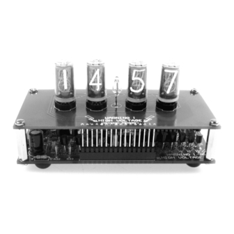
Features & Specifications Grab your chance NOW, build your own nixie clock. Limited edition! What are ‘nixie’-tubes ? Nixie tubes are the ‘LED indicators’ of the past. In the 50’s, 60’s and early 70’s there were no LED’s or LCD’s. Neon gas filled tubes were used to display numerical data. -
Page 3: Assembly Hints
Assembly hints 1. Assembly (Skipping this can lead to troubles ! ) Ok, so we have your attention. These hints will help you to make this project successful. Read them carefully. 1.1 Make sure you have the right tools: • A good quality soldering iron (25-40W) with a small tip. - Page 4 Assembly hints 1.3 Soldering Hints : 1- Mount the component against the PCB surface and carefully solder the leads 2- Make sure the solder joints are cone-shaped and shiny 3- Trim excess leads as close as possible to the solder joint REMOVE THEM FROM THE TAPE ONE AT A TIME ! AXIAL COMPONENTS ARE TAPED IN THE CORRECT MOUNTING SEQUENCE !
-
Page 5: Main Board
Construction IMPORTANT! This kit generates high voltages. Always use a suitable enclosure for this kit! The Kit consists of 2 boards. One for the electronics and one for the Nixie, display tubes Unpack, inspect and handle the tubes with care! All components are mounted on a “double side”... - Page 6 construction 3. Fast diode. Watch the 6. Voltage regulator 9. Vertical resistors polarity! VR1 : 7805 R... D6 : UF4007 7. MOSFET transistors 4. IC socket. Watch the R14 ... R31 : 10K (1 - 0 - 3 - B) position of the notch! R32 ...
- Page 7 Construction 11. Connector 14. Fuse. 17. Main board test !!CAUTION HIGH VOLTAGES!! F1 : 1A DO NOT TOUCH THE BOARD Connect a 12Vac (not DC!) adaptor to the board. Carefully measure about 180Vdc between ground (eg metal part of VR1) and cathode (white stripe) of D6. 12.
-
Page 8: Display Pcb
Test & display DISPLAY PCB 1. Female header connector 3. Neon tube Solder the female header connector to the display board. Mount the neon tube as connections at solder side! straight as possible. 2 Tubes Mount the nixie tubes as straight as possible Take care not to bend the leads! First solder 1 connection of EACH tube Align and straighten the tubes, then solder a second con-... -
Page 9: Final Test
Solder the connector to the main board, and cut M3 6mm bolt the connector left over. ! use 16mm bolts if K8099 used with B8099 FINAL TEST Connect the 12Vac to the board, if all works well, the displays should light. Check the user manual for further set-up... - Page 10 Configuring and setting CONFIGURING AND SETTING YOUR CLOCK 50Hz AC: OK 50Hz AC: OK 50Hz AC: OK Apply 9-12VAC. The clock will display '50' or '60' for 3s, depending on the AC power frequency (Hz) in your area. This indicates that the zero cross detection part of the clock circuit is working fine.
- Page 11 Configuring and setting Show this hour Show this hour Show this hour To save energy and extend tube life, the unit allows you to blank the display for certain periods (e.g. at night, while you are absent, etc...) The digits on the left hand side of the separator indicate the hours (00 to 23).
- Page 12 Schematic diagram Schematic diagram "base"...
- Page 13 Schematic diagram Schematic diagram "display"...
- Page 14 Main PCB...
- Page 15 Display PCB...
- Page 16 Modifications and typographical errors reserved VELLEMAN NV © Velleman nv. Legen Heirweg 33, 9890 Gavere H8099IP'1 - 2009 Belgium - Europe 5 4 1 0 3 2 9 4 2 1 7 2 4...


