Table of Contents
Advertisement
Advertisement
Table of Contents

Summary of Contents for Dahua ipc-hdbw2300r-z
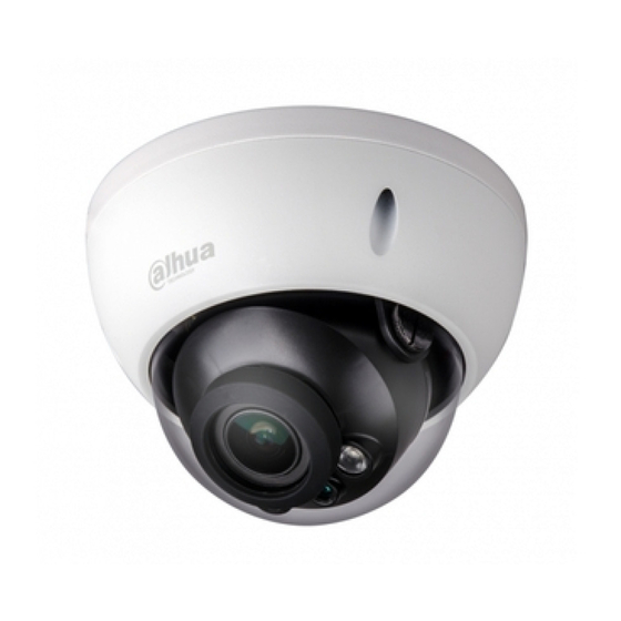
- Page 1 HD IR Vari-focal Dome Network Camera Quick Start Guide Version 1.0.0...
- Page 2 Welcome Thank you for purchasing our network camera! This quick start guide is designed to be a reference tool for your system. Please keep this start guide well for future reference. Please open the accessory bag to check the items one by one in accordance with the list below. Contact your local retailer ASAP if something is missing or damaged in the bag.
- Page 3 Thunder-proof device is recommended to be adopted to better prevent thunder. The grounding studs of the product are recommended to be grounded to further enhance the reliability of the camera. 6. Daily Maintenance Please shut down the device and then unplug the power cable before you begin daily maintenance work.
-
Page 4: Table Of Contents
Table of Contents Structure ............................. 1 Components ........................1 Framework and Dimension ..................2 Alarm Setup ........................2 Device Installation ........................5 Installation Steps ......................5 Micro SD Card Installation ..................6 Lens Adjustment ......................7 Quick Configuration Tool ......................8 Overview ........................ -
Page 5: Structure
1 Structure 1.1 Components Note: There are differences about wire structure for some product models, please refer to the actual object for more details. You can refer to the following figure for component structure. See Figure 1-1. Figure 1-1 Please refer to the following sheet for detailed information. Component Component Name Component 1... -
Page 6: Framework And Dimension
Port Port Name Note Power input port Port 3 Connect to DC 12V power, input power. Alarm signal input/output (optional, Port 4 I/O port supported by some product models) Network data in/out and PoE. Port 5 Internet access port Note: ... - Page 7 Only supported by some series products. Alarm input, output description: Step 1 Connect alarm input device to the alarm input of I/O cable. Step 2 Connect alarm output device to the alarm output of I/O cable, alarm output is collector open circuit output which connects 10K resistor to 3.3V externally.
- Page 8 Figure 1-4...
-
Page 9: Device Installation
2 Device Installation 2.1 Installation Steps Manual Focus Camera Motorized Vari-focal Camera Figure 2-1 Important Before the installation, please make sure the installation environments can at least support 3x weight of the camera. Please follow the steps listed below to install the device. Please refer to Figure 2- for reference. Step 1 Use inner hex wrench in the accessories bag to open dome enclosure by unfastening three inner hex screws on enclosure. -
Page 10: Micro Sd Card Installation
Hold rotating bracket on both sides with hand, horizontally rotate bracket, adjusting lens horizontal direction to designated position. Loosen two hand screws on both sides of fixed rotating bracket. (Loosen only, do not take it down), hold the camera module body with hand, making lens rotate vertically. -
Page 11: Lens Adjustment
Figure 2-3 Micro SD Card installation illustration 1 Figure 2-4 Micro SD Card installation illustration 2 2.3 Lens Adjustment After you take off the dome housing, you will see the adjusting screw nut of the lens, adjusting screw nut C is for zoom function, adjusting screw nut D is for focus function. Make sure to lock the adjusting screw after the image is clear. -
Page 12: Quick Configuration Tool
3 Quick Configuration Tool 3.1 Overview Quick configuration tool can search current IP address, modify IP address. At the same time, you can use it to upgrade the device. Please note the tool only applies to the IP addresses in the same segment. 3.2 Operation Double click the “ConfigTools.exe”... - Page 13 Figure 3-2 Login prompt After you logged in, the configuration tool main interface is shown as below. See Figure 3-3. Figure 3-3 Main interface For detailed information and operation instruction of the quick configuration tool, please refer to the Quick Configuration Tool User’s Manual included in the resources CD.
-
Page 14: Web Operation
4 Web Operation This series network camera products support the Web access and management via PC. Web includes several modules: Monitor channel preview, system configuration, alarm and etc. 4.1 Network Connection Please follow the steps listed below for network connection. ... - Page 15 Figure 4- 2 Web login After you successfully logged in, please install WEB plug-in unit. Please refer to the Web Operation Manual included in the resource CD for detailed operation instruction. See Figure 4- 3. Figure 4- 3 Web monitoring window...
-
Page 16: Appendix Toxic Or Hazardous Materials Or Elements
Appendix Toxic or Hazardous Materials or Elements Toxic or Hazardous Materials or Elements Component Name Cr VI PBDE Circuit Board ○ ○ ○ ○ ○ ○ Component ○ ○ ○ ○ ○ ○ Device Case ○ ○ ○ ○ ○ ○...


