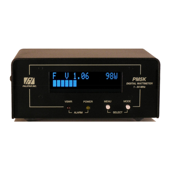
Summary of Contents for Palstar PM5K
- Page 1 Palstar Incorporated PM5K Digital Wattmeter 9676 N. Looney Rd., Piqua, OH 45356 USA Owner s Manual Customer Service and Sales Telephone: 1-800-773-7931 Fax: 1-937-773-8003 Email: info@palstar.com © Copyright 2007 Palstar Inc. Printed in the U.S.A.
-
Page 2: Table Of Contents
PM5K WATTMETER PM5K WATTMETER Notes: TABLE OF CONTENTS Unpacking and Setup Introduction Quick Setup Installation General Operation Using the PM5K Front Panel Rear Panel Connections Remote Coupler Mounting Directional Coupler Mounting Accuracy and Calibration In Case of Trouble Specifications Warranty 1-800-773-7931 WWW.PALSTAR.COM... -
Page 3: Unpacking And Setup
Turn on the power to the Display Head. You should see the by anyone other than Palstar with- out prior written authorization. War- firmware version number displayed, and then the PM5K will go to ranty does not extend to any prod- its normal operational state. -
Page 4: Introduction
(see accuracy section on nals. The PM5K also features the ability to be monitored and con- how to achieve better accuracy) trolled from a PC via the bundled software, and the unique ability... - Page 5 PM5K WATTMETER PM5K WATTMETER SPECIFICATIONS Specifications subject to change without notice. Write your new PM5K serial number and calibration data for your coupler here (see coupler sticker): Frequency Range Line Impedance Insertion Loss Serial Number __________________________________ Line Connections Power Ranges...
-
Page 6: Quick Setup
ANTENNA goes to your antenna (or tuner) High VSWR displayed; no forward power displayed For the 5 kW PM5K or 10 kW PM10K, plug the ¼ connector into the Directional Coupler and Display Enclosure. Supply 12V DC Be sure that the SOURCE input to the Directional Coupler power by connecting a standard 2.1 mm coaxial plug to the DC... -
Page 7: Installation
DIRECTIONAL COUPLER WIRING - Since the purpose of the your meter to match your coupler for the frequencies you PM5K is to provide an indication of the match of your antenna sys- will use. We typically see +/- 3% accuracy at HF and tem to your transmitter, it is critical that the Directional Coupler be even better at the 6 meter band. -
Page 8: General Operation
In addition to the large vacuum fluorescent display, there are two A Power/VSWR meter that requires you to run coax to it since it buttons on the front of the PM5K: Menu and Mode Select. has no remote coupler means you have to mount the meter very close to your operating position. -
Page 9: Using The Pm5K Front Panel
PM5K WATTMETER PM5K WATTMETER REAR PANEL CONNECTIONS USING THE PM5K Power Monitor Alarm stereo jack, relay will close or open depending on how RS232 connect a you program it, these are .5 Front Panel Controls DB9 cable to a PC amp 50V contacts. - Page 10 PC. Just download the latest revision of Pushing the menu button again takes us to the next menu item. firmware from Palstar: www.palstar.com/pm5k.php. See the LIT software manuals on the CD for the procedure. Alarm Polarity Menu...
- Page 11 PM5K WATTMETER PM5K WATTMETER Reverse Power Trim Menu Low Power Alarm Menu Select with mode select button to scroll from Push the mode select button to choose trip point in watts: +15% to -10%. Set the Reverse Power Trim factor to the settings indicated on your coupler for HF (30MHz setting).
- Page 12 PM5K WATTMETER PM5K WATTMETER Alarm Trips Amp Menu Display Intensity Menu Range: 1 - 4 (brightest) Select with mode select button: Select with mode select button : This menu option allows the high power alarm to actuate the PTT/ ALC relay just like a VSWR alarm does.


