Summary of Contents for H3C RPS800-A
- Page 1 RPS800-A User Manual Hangzhou H3C Technologies Co., Ltd. http://www.h3c.com Manual Version: 20080428-C-1.01...
- Page 2 Copyright © 2007-2008, Hangzhou H3C Technologies Co., Ltd. and its licensors All Rights Reserved No part of this manual may be reproduced or transmitted in any form or by any means without prior written consent of Hangzhou H3C Technologies Co., Ltd.
- Page 3 To obtain the latest information, please access: http://www.h3c.com Technical Support customer_service@h3c.com http://www.h3c.com Environmental Protection This product has been designed to comply with the requirements on environmental protection.
-
Page 4: Table Of Contents
Table of Contents 1 Packing List............1 2 Product Overview ..........1 2.1 Introduction ...........1 2.2 Features ............3 2.3 Front Panel............4 2.4 Rear Panel ............4 2.5 LEDs .............4 2.6 Technical Specifications........5 3 Installation............7 3.1 Precautions ...........7 3.2 Installing the RPS Unit ........9 3.2.1 Installing the RPS Unit to a 19-inch Rack ..............10 3.2.2 Installing the RPS Unit on a Tabletop .11... -
Page 5: Packing List
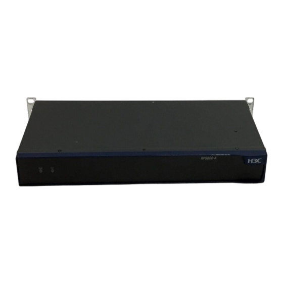
Rack-mounting ear screws Foot pads 2 Product Overview 2.1 Introduction The RPS800-A is an external DC power supply unit that uses AC input and provides DC output for multiple switch and router models as a redundant backup power supply system. - Page 6 RPS unit only works in the monitoring mode, without feeding power to the powered device. The output of the RPS800-A is controlled by a control pin. When the powered device’s own power supply system becomes fails, a LOW signal is sent to the control pin of the RPS unit.
-
Page 7: Features
Note: For some models of powered devices, the control pin of the RPS800-A can be controlled through a special cable to support hot backup of power supply. Namely, when the power supply systems of the powered devices operate normally, the RPS unit also provides part of the power feed to the devices;... -
Page 8: Front Panel
2.3 Front Panel (1) AC Input LED (PWR) (2) DC output LED (OUT) Figure 1 Front panel of the RPS800-A 2.4 Rear Panel (1) Grounding screw (2) AC input (3) DC output Figure 2 Rear panel of the RPS800-A 2.5 LEDs... -
Page 9: Technical Specifications
RPS. Note: The OUT LED lights up only when the RPS800-A switches to the DC output state. When the RPS800-A works in the monitoring mode, its OUT LED stays off. 2.6 Technical Specifications... - Page 10 Item Specifications –54 V/12 A Available Outputs +12 V/17.25 A +12 V output 210 W only Maximu –54 V output 650 W m power only consum 210 W for +12 V output ption +12 V and –54 V outputs 440 W for –54 V output simultaneously Total: <...
-
Page 11: Installation
3 Installation 3.1 Precautions To avoid any device impairment or bodily injury because of improper use, follow the precautions listed below: Do not place the RPS unit on an unstable case or tabletop, and ensure that the cabinet and the workbench are firm enough to support the RPS unit and its accessories. - Page 12 multi-functional power socket for computers. Make sure that the neutral point of the power source is well grounded. Make sure that the power source satisfies the voltage requirement of the RPS unit. Interface cables must be routed indoors. Otherwise, over-voltage and over-current may damage the device.
-
Page 13: Installing The Rps Unit
Note: Dust particle size ≥ 5µm Table 5 Limits on harmful gas concentration Limit (mg/m 0.006 0.05 0.01 3.2 Installing the RPS Unit The RPS800-A can be installed either in a 19-inch standard rack or directly on a tabletop. -
Page 14: Installing The Rps Unit To A 19-Inch Rack
RPS unit to the rack; they cannot bear the weight of the RPS unit. When installing the RPS800-A to a 19-inch rack, be sure to use a tray or bracket to support the weight of the unit. Step 1: Put on an ESD-preventive wrist strap and check the grounding and stableness of the rack. -
Page 15: Installing The Rps Unit On A Tabletop
Step 4: Place the RPS unit horizontally on the supporting tray, gently push the unit into the rack along the supporting tray, and fix the mounting ears to the front square-holed brackets of the rack with screws and cage nuts, as shown in Figure 4 . Front square-holed bracket Front mounting ear... -
Page 16: Connecting The Rps Unit To The Powered Device
3.3 Connecting the RPS Unit to the Powered Device The RPS800-A can be used as a redundant backup power supply unit for multiple switch and router models. The following describes how to connect the RPS unit to a switch. - Page 17 Step 5: Check that the PWR LED on the front panel of the RPS unit lights up. Note: The OUT LED lights up only when the RPS800-A switches to the DC output state. When the RPS800-A works in the monitoring mode, its OUT...


