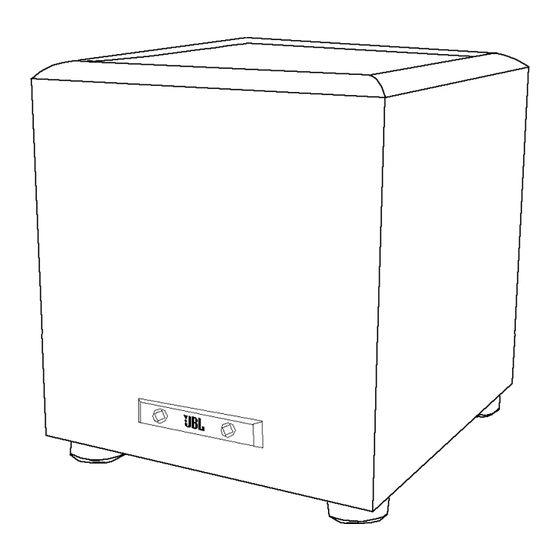
JBL PowerBass Series PB10 Preliminary Service Manual
Hide thumbs
Also See for PowerBass Series PB10:
- Owner's manual (9 pages) ,
- Service manual (54 pages) ,
- Service manual (28 pages)
Summary of Contents for JBL PowerBass Series PB10
- Page 1 PowerBass Series PB10 Subwoofer PRELIMINARY SERVICE MANUAL JBL Incorporated, Inc. 250 Crossways Park Dr. Woodbury, New York 11797...
-
Page 2: Table Of Contents
- CONTENTS - BASIC SPECIFICATIONS ……………………….…….……………..……………..2 DETAILED PB10 SPECIFICATIONS…………………….……….……..……………..3 CONNECTIONS…………………………………………………..……………..………..4 OPERATION………………………………….……………………………………..…….8 TROUBLESHOOTING…………………….…………….………………..….……..…….9 ELECTRICAL PARTS LIST ……………….…………..…………..……………….…10 MECHANICAL/PACKING PARTS LIST……………….……..……..……………….…14 PCB DRAWINGS……………….…………..……………….………..….………………15 SCHEMATICS ………..……………………..………………...…….………………..18... - Page 3 (with feet) 16" x 14" x 15" 406mm x 356mm x 381mm 35 lb/15.9kg Weight Refinements may be made on occasion to existing products without notice but will always meet or exceed original specifications unless otherwise stated. PowerBass is a registered trademark of JBL Incorporated.
-
Page 4: Basic Specifications Detailed Pb10 Specifications
JBL PB 10 150W Powered Sub Amp LINE VOLTAGE Yes/No Hi/Lo Line Nom. Unit Notes US 120vac/60Hz 108-132 Vrms Normal Operation EU 230vac/50-60Hz 207-264 Vrms Normal operation, MOMS required QA Test Parameter Specification Unit Limits Conditions Notes Amp Section Type (Class AB, D, other) Class D Preferred...Sink required for Class AB... -
Page 5: Connections
S P E A K E R C O N N E C T I O N When we designed the examples to determine which post is visible under the collar. PB10 and PB12 powered description best matches your Insert the bare end of the wire subwoofers, our goal was system and follow the through the hole in the post,... -
Page 6: Speaker Connection/Level
S P E A K E R C O N N E C T I O N When we designed the examples to determine which post is visible under the collar. PB10 and PB12 powered description best matches your Insert the bare end of the wire subwoofers, our goal was system and follow the through the hole in the post,... -
Page 7: Dolby Pro Logic Line Level
Dolby Pro Logic (Non-Digital) – Line Level Use this installation method use the “LFE” position with Make sure your receiver or for Dolby Pro Logic appli- Dolby Pro Logic-only processor is configured cor- cations (not Dolby Digital, DTS processors. rectly: Make sure that the sub- or other digital processing), woofer is configured as “On.”... -
Page 8: Dolby Digital Or Dts Connection
Dolby Digital or DTS (or Other Digital Surround Mode) Connection Use this installation method then you may connect the center and rear speakers for Dolby Digital, DTS or other subwoofer output on your should be set to “Small” or digital surround processors: receiver/preamplifier to either “Large”... -
Page 9: Operation
(for the PB12 only) the input signal to the subwoofer The PB10 must be unplugged power switch is on and no is removed. Due to JBL’s if you do not wish to leave it in signal is received, the LEDs on unique, high-output, high- auto (standby) mode. -
Page 10: Troubleshooting
Phase Control The Phase Control determines bass output at the listening in the future you happen to whether the subwoofer’s position. rearrange your listening room piston-like action moves in and move your speakers, you Remember, every system, and out in phase with the should experiment with the room and listener is different. -
Page 11: Electrical Parts List
Electrical Parts List- PB10 PB10 POWER AMP section of PCB Version 6.3. Part# Designator Description Semiconductors 60102 TLO64 Quad OpAmp 50100 RS604 6AMP BR RECT 50105 1N4744A 1w Zener 50112 1N5242B .5w Zener 50104 1N4148 Sig Diode 50112 1N5242B .5w Zener 50104 1N4148 Sig Diode... - Page 12 Part# Designator Description Resistors R100 NOT USED 40105 R10A 0.1R 0.05 metal 40105 R10B 0.1R 0.05 metal 40105 R10C 0.1R 0.05 metal 40420 .25W 0.05 carbon 40420 .25W 0.05 carbon 40417 .25W 0.05 carbon 40718 .25W 0.05 carbon 40406 100k .25W 0.05 carbon 40719...
- Page 13 Part# Designator Description 40728 0.05 metal 40728 0.05 metal 40728 0.05 metal 40729 0.05 metal 40729 0.05 metal NOT USED Miscellaneous 80101 110uH Gapped E-core choke 80102 2.2uH 2.2uH ferrite bead 0-R Jumper 0-R Jumper 80100 2m2H 5 Amp 0.05 2.2mH choke 60301 MODULE S53AMI amp module...
- Page 14 Part# Designator Description 30519 100nF 0.2 mono ceramic 30519 100nF 0.2 mono ceramic 30519 100nF 0.2 mono ceramic 30519 100nF 0.2 mono ceramic 30101 220pF 0.2 mono ceramic NOT USED 30101 220pF 0.2 mono ceramic 30101 220pF 0.2 mono ceramic 30101 220p 0.2 mono ceramic...
-
Page 15: Mechanical/Packing Parts List
MECHANICAL & PACKING PARTS LIST Part# Description 203400 10” Woofer 203410 Foot 203420 Outer Carton 203430 Owner’s manual 120V 203450 Amplifier complete... -
Page 16: Pcb Drawings
Vers63.gbl (Board layer 1) Scale=1.20 Wed May 17 08:26:14 2000... - Page 17 Vers63.gtl (Board layer 1) Scale=1.20 Wed May 17 08:36:44 2000...
- Page 18 Vers63.gto (Board layer 1) Scale=1.36 Wed May 17 08:38:34 2000...
-
Page 19: Schematics
3rd Order Hi-Pass DUALRCA LEVEL 68k1 604r REMOTE Pot 57k6 5k POT SW SPDT R In 33k2 330pF 220p 45k3 330pF Phase Switch LM324 LM324 NOT USED 330nF 330nF 330nF 33k2 L In 33k2 137k 11k3 243k 604r RCA CONNECTOR Binding Post 220pF 2nd Order Hi-Pass... - Page 20 LED1/2 Preamp LED1/2 Preamp 1000k SIGNAL LED & AUTO MUTE Not Used LED Harness V+ LED 470K 1N4148 TLO64 R100 NOT USED Un-designated Connector TLO64 On Harness On Harness MOLEX 2 MOLEX 2 1N4148 To U1 Pin 11 1N4148 +15V 1N5242B mute 1000k...


