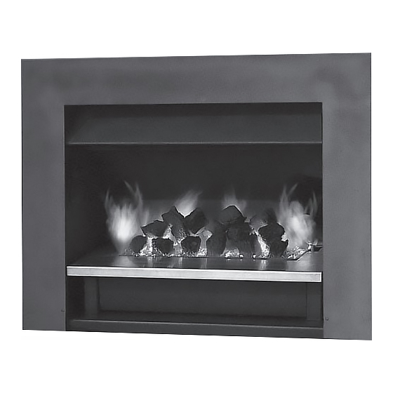
Summary of Contents for Jetmaster Mark 2
- Page 1 Installation instructions Jetmaster Mark 2 Gas Coal / Pebble with Millivolt Control...
-
Page 2: Location Requirements
Installation instructions Jetmaster Mark 2 Gas Coal / Pebble Jetmaster gas coal / pebble burners are fuel effect Location Requirements appliances intended for use in a fireplace suitable for the 1. The fireplace construction must be non-combustible burning of wood. It is recommended that the Jetmaster... -
Page 3: Lighting Instructions
If it goes out repeat ignition procedure. clear prior to fitting. 3. In an existing fireplace or Jetmaster firebox (if being used) drill MAIN BURNER IGNITION a 15mm hole through the right hand side of the fireplace(as you... - Page 4 HOW TO ADJUST GAS PRESSURE...
- Page 5 MARK 2 COALS 440 / 500 - 390 X 240 MARK 2 COALS 600 - 460 X 260 MARK 2 COALS 700 - 580 X 260...
-
Page 6: Commissioning Procedure
Jetmaster firebox which has been designed to ensure a proper draw and to eliminate emission spillage. 2. Initially the Jetmaster coal / pebble fire may burn with a slightly blue flame.After approximately 20 minutes the fire will settle down and burn with a yellow flame. -
Page 7: Specifications
SPECIFICATIONS NAME OF APPLIANCE: JETMASTER GAS COAL MARK 2 KEMLAN GAS COAL MARK 2 WITH MILLIVOLT IGNITION MANUFACTURED BY: JETMASTER FIREPLACES AUSTRALIA PTY LTD. CERTIFICATE NO. 4958 LABORATORY REPORTS: 511285, 511286,511389. DATE: MAY 1994 The gas fire is a Type 1 Decorative gas coal fire with imitation coals or pebbles (700MK2P/C and 800MK2P/C) placed over a bed of vermiculite contained within a metal tray. - Page 8 OVERALL DIMENSIONS: See drawings supplied 400/500 Grate * 600 Grate *700 Grate *800 Grate Width 390mm 460mm 580mm 740mm Height 210mm 210mm 210mm 210mm Depth 240mm 260mm 260mm 320mm Weight 12kg 15kg 18kg * 400 Burner is the same as 500 Burner but does not have two decorative legs on the outer grate.
-
Page 9: Gas System
GAS SYSTEM Gas inlet connection: Flared ½” inlet and is located on the right hand side of the gas grate. Regulator: Beckley Type A.G.A. App. No. 4688(Nat gas only) 3/B BSP Female for LPG Bromic Type BMWF1A A.G.A. App. No. 5149 Piping: 5/16”... - Page 10 CONVERSION DETAILS Remove injectors by unscrewing nuts in venturi. Replace with injector specified on date plate. The appropriate injector must be used (see data plate). Replace pilot assembly to appropriate gas. Pilot assembly must be replaced with appropriate models. Regulator is required to be fitted to a natural gas appliance. For LPG the appliance regulator requires removal.
- Page 11 GENERAL GUIDE FOR SET-UP OF NOVA MV SYSTEM. 1). Bleed all air from gas lines. 2). With the main burner functioning, adjust the inlet pressure regulator to supply gas to the appliance within the design parameters of the appliance manufacturer. 3).
- Page 12 PROBLEM POSSIBLE CAUSE SOLUTION Pilot will not light No gas 1)Bleed air from gas line. 2)Check stop cocks are in on position.(No blockage in line) Wrong inlet pressure Adjust inlet pressure with main burner running.(see diagram) Defective spark Replace electrode if the insulator is electrode.
- Page 13 Defective safety Verify operation of safety magnet in the magnet.(mV Plus following manner. systems) (A) Depress and hold pilot button. (B) Verify open-circuit thermocouple voltage as described in previous step. © Reconnect thermocouple to valve. (D) Measure the Millivoltage between the solder button on the base of the safety magnet, and the valve body.
- Page 14 Defective thermostat or (A) With the pilot adjusted properly, thermostat wiring. (Set-up section, step#7), place a jumper wire between TPTH and TH. Take a mV reading across the TPTH and TP terminals on the valve. This closed circuit voltage should not fall below 300mV.
- Page 15 Notes For further information contact Jetmaster Australia 10 Martin Avenue, Arncliffe NSW 2205 T: 02 9597 7222 F: 02 9597 7622 E: sales@jetmaster.com.au W: www.jetmaster.com.au...


