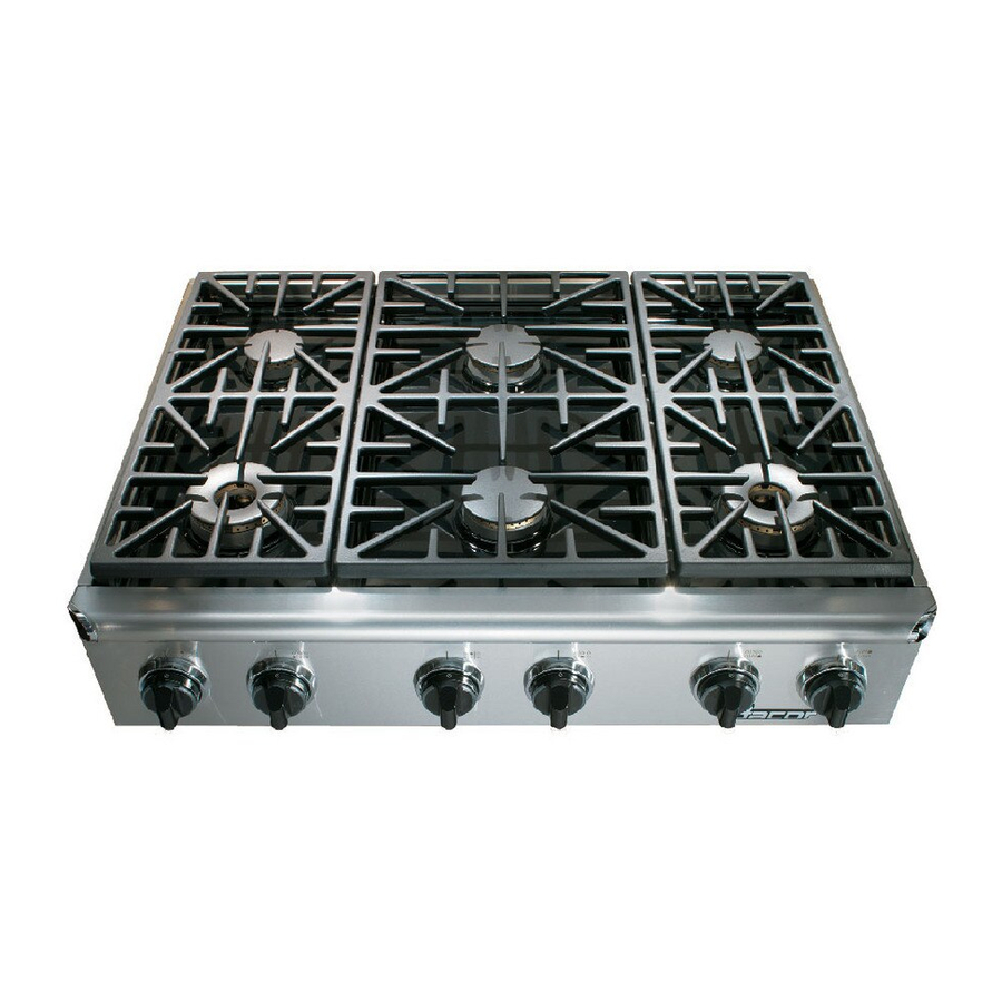
Dacor Epicure EG366 Installation Instructions Manual
Hide thumbs
Also See for Epicure EG366:
- Use and care manual (21 pages) ,
- Installation instructions manual (19 pages) ,
- Instructions (4 pages)
Table of Contents
Advertisement
Quick Links
Advertisement
Table of Contents

Summary of Contents for Dacor Epicure EG366
- Page 1 Install atIon InstructIons ® EpIcurE cooktop For Use with Models: EG366, EG486 Save TheSe InSTrucTIonS ThIS aPPLIance haS Been TeSTeD In accorDance WITh The LaTeST eDITIon oF anSI Z21.1 STanDarD For houSehoLD GaS aPPLIanceS. Part No. 102025 Rev. K...
- Page 2 ® all specifications subject to change without notice. Dacor assumes no liability for changes to specifications. © 2007 Dacor, all rights reserved.
-
Page 3: Table Of Contents
IMPorTanT: If you have questions or problems with installation, contact your Dacor dealer or the Dacor Customer Service Team. • nSTaLLer: In the interest of safety and to minimize Dacor customer Service Team problems, read these installation instructions... -
Page 4: Important Safety Instructions
AEB3609, AEB3612, AEB4809, AEB4812 or a non-combustible material. † See the latest version of ANSI Z223.1. Do not use this appliance in combination with a surface (countertop) ventilation system. Dacor strongly recommends the instal- lation of a range hood in conjunction with this appliance. -
Page 5: Customer Service Information
You can fight the fire with your back to an exit. customEr sErvIcE InformatIon any questions or problems with this installation Model Identification should be directed to your Dacor dealer or the Dacor eG366Sch/nG/h customer Service Team. Dacor Customer Service Team SIZe (in inches) 1-800-793-0093 (U.S.A. -
Page 6: Planning The Installation
plannIng thE InstallatIon WarnInG IMPorTanT: Observe all governing codes and ordinances during planning and installation. Contact your local building department for further information. ElEctrIcal rEquIrEmEnts product dImEnsIons • It is the owner’s responsibility to ensure that the electrical receptacle for this appliance has been installed by a qualified electrician. -
Page 7: Cabinet Layout
• To reduce the risk of personal injury and to reduce General considerations accumulated smoke in the room, Dacor strongly recommends • installing a hood. A range hood should project horizontally a All dimensions shown on the following pages are based on minimum of five (5) inches beyond the face of the cabinets. - Page 8 plannIng thE InstallatIon cabInEt layout (contInuEd) Hood 30” (457mm) Minimum 1 1/2” (38mm) 18” Typical countertop 10” (254mm) to 5/8” (16mm) (457mm) thickness combustible side wall Overhang, Minimum minimum, both sides both sides 7 3/4” (197mm) 2 3/4” (70mm) Cooktop platform 15 1/2”...
- Page 9 plannIng thE InstallatIon cabInEt layout (contInuEd) All tolerances: +1/16”, -0 (+1.6mm, -0) Non combustible rear wall 8” (203mm) 6” Hole 2 Places, 1/2” Dia. Utility Cut-out to allow (152mm) through cooktop platform for gas and electrical 12 9/16” for hold-down bolts connection below (319mm) 24”...
- Page 10 plannIng thE InstallatIon cabInEt layout (contInuEd) Backsplash Max.3/4" (19mm) Vertical non-combustible surface rear wall 2 13/16" EG366: 33 7/8" (860mm) (71mm) EG486: 43 1/2" (1105mm) 1/4" (6mm) Min. flat ledge Open to Below EG366: 7/16" (11mm) 3/4” Support EG486: 1 5/8" (41mm) Platform Both sides 21 3/8"...
-
Page 11: Installation Instructions
InstallatIon InstructIons prEparIng for InstallatIon cooktop InstallatIon IMPorTanT: Within the Commonwealth of Massachusetts, cauTIon this appliance must be installed by a licensed plumber or To prevent damage to the gas pressure regulator, install the gas fitter. regulator only after the cooktop is mounted in its permanent position. -
Page 12: Cooktop Setup
InstallatIon InstructIons cooktop sEtup WarnInG Never attempt to operate the cooktop with any of the burner Spill Tray rings, burner caps or grates removed. crown Burner Install the Burner components noTe: Do not attempt to adjust the burner air mixture Stack Burner settings. - Page 13 InstallatIon InstructIons Installing the Burner Knobs cauTIon Installing the cooktop knobs in the wrong position may result in damage to the cooktop griddle. The knobs for the center burners are marked with the maximum griddle settings. There are two (2) different types of knobs supplied with the cooktop.
-
Page 14: Verifying Proper Operation
• Proper installation is the responsibility of the homeowner. accompanying use and care manual carefully. Important The importance of proper installation of your Dacor cooktop safety, service and warranty information is contained within cannot be overemphasized. the use and care manual. -
Page 15: Notes
notEs... - Page 16 Dacor ● 1440 Bridge Gate Drive, Diamond Bar, CA 91765 ● Tel: (800) 793-0093 ● FAX: (626) 403-3130 ● www.Dacor.com...


