
Related Manuals for Xtreme Power Conversion P90 1000VA


Summary of Contents for Xtreme Power Conversion P90 1000VA
- Page 1 P90 Online UPS 1000VA, 1500VA, 2000VA, 3000VA Models User & Installation Manual www.xpcc.com | © 2015 Xtreme Power Conversion Corporation. All rights reserved. (Rev 4/08/15)
-
Page 2: Table Of Contents
Battery Replacement........................17 Operations....................20 Button Operation.......................... 20 LCD Panel............................20 Audible Alarms..........................22 Abbreviations in LCD Display......................22 UPS Setting............................23 Operating Mode Description......................27 Fault Reference Codes........................28 Warning Indicators........................29 Troubleshooting..................30 Storage And Maintenance................32 Storage............................32 Maintenance..........................32 Batteries.....................32 Specifications.....................33 Shipping List....................33 Xtreme Power Conversion Corporation Page 2... - Page 3 P90 User’s Manual Uninterruptible Power Supply Obtaining Service..................34 Xtreme Power Conversion Limited Warranty..........35 Xtreme Power Conversion Load Protection Policy........36 Appendix A: P90-BP48 & P90-BP72 User Guide...........39 Important Safety Instructions......................39 Product Overview and Setup......................39 Type of Battery Required.......................41 Battery Replacement........................42 Wiring Diagram..........................46 Storage &...
- Page 4 These UPS units are extremely heavy. Caution should be taken in moving and positioning equipment. The instructions contained within this safety manual are deemed important and should be closely followed at all times during installation and follow-up maintenance of the UPS and batteries. Xtreme Power Conversion Corporation Page 4...
- Page 5 RJ45 RECEPTACLE – The receptacle provides network interface connections and telephone or telecommunications equipment should not be plugged into it. Please do not discard the UPS or the UPS batteries as the UPS may have valve-regulated lead-acid batter- ies. Please recycle batteries appropriately. Xtreme Power Conversion Corporation Page 5...
-
Page 6: Introduction
• DC power is converted to AC in the inverter, passing it on to the load. • Power is maintained from the battery during a power failure. • The converter increases voltage appropriately for the inverter. Xtreme Power Conversion Corporation Page 6... -
Page 7: Diagnostic Tests
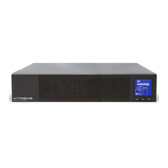
Connectivity Options – Web/SNMP Card, Relay Card, Modbus Card Battery packs, rail kits, bypass switches See the Specification section of this manual for additional model information. P90 front view P90-1000 rear view P90-1500 rear view Xtreme Power Conversion Corporation Page 7... - Page 8 P90 User’s Manual Uninterruptible Power Supply P90-2000 rear view P90-3000 rear view Front panel Selector buttons Rack display Xtreme Power Conversion Corporation Page 8...
-
Page 9: Communication Connections
It can support op- erating systems such as HP Open View, IBM Netview, SUN Netmanager, etc. This enables the UPS to provide instant UPS and power information over the network. Please contact your reseller for additional details. Xtreme Power Conversion Corporation Page 9... -
Page 10: Emergency Power Off (Epo) Port
The UPS will have to be manually restarted in order to regain power to the outlets on the UPS. Keep Pin 1 and Pin 2 closed for UPS normal operation. To activate EPO function, open the wire between Pin 1 and Pin 2. Xtreme Power Conversion Corporation Page 10... -
Page 11: Hardware Installation Guide
• Space and ventilation requirements must be met. Ensure there is 100mm behind and 50mm on the sides of the UPS for proper ventilation. • Ensure that the front of the UPS remains clear for user operation. Xtreme Power Conversion Corporation Page 11... -
Page 12: Ups Installation
UPS, please follow these steps to connect the battery wires. Connecting the batteries Step 1 Remove the front panel Step 2 Connect the battery wires Step 3 Place the front cover back on the front of the UPS Xtreme Power Conversion Corporation Page 12... - Page 13 Slide the UPS into the rack and secure using hardware provided Rack-mount Installation (using 4-post rail kit) Package contents • Right and left rail sliders, 1 each • (2) M6 nuts • (12) M6 screws Xtreme Power Conversion Corporation Page 13...
- Page 14 Use 4 screws to mount right and left rail sliders in front of rack. Step 2 Use 4 screws to mount right and left rail sliders in back of rack. Step 3 Place the nuts in the proper location in the rack based upon height of UPS. Xtreme Power Conversion Corporation Page 14...
- Page 15 P90 User’s Manual Uninterruptible Power Supply Step 4 Carefully place the UPS on the rail support. Step 5 Fix the UPS in position with screws. Step 6 Rail kit installation is now complete. Xtreme Power Conversion Corporation Page 15...
- Page 16 Inter-connect the tower brackets that shipped in the box with the UPS Step 2 Carefully lower the UPS into the brackets as shown Step 3 Your UPS is now mounted as shown in the tower position Xtreme Power Conversion Corporation Page 16...
-
Page 17: Starting The Ups
CAUTION: Consider all Safety Warnings in previous sections of this manual before proceeding with the battery tray replacement. NOTE: Please beware that once the battery tray is disconnected from the UPS, the equipment connected to the output of the UPS is not protected from power outages. Xtreme Power Conversion Corporation Page 17... - Page 18 Step 1 Remove the front panel Step 2 Disconnect the battery tray connector from the UPS Step 3 Step 3 Pull out the battery tray by removing the two screws on the front panel Xtreme Power Conversion Corporation Page 18...
- Page 19 UPS and secure with the two screws to the front panel Step 5 Reconnect the battery tray connector to the UPS Step 6 Place the front cover back on the front of the UPS Xtreme Power Conversion Corporation Page 19...
-
Page 20: Operations
SELECT buttons simultaneously for 5 seconds. The UPS will then enter ON/Mute + Select Button Bypass mode. The Bypass mode will be disabled when the input voltage is out of acceptable range. LCD Panel Rack Display Tower Display Xtreme Power Conversion Corporation Page 20... - Page 21 Indicates the UPS is working in converter mode. Indicates the UPS is working in bypass mode. Indicates the UPS is powering the output directly from utility. Indicates that the UPS alarm is disabled. Indicates the battery charger is working. Xtreme Power Conversion Corporation Page 21...
-
Page 22: Audible Alarms
Sounds every second Overload Sounding twice every second Fault Continuously sounds Abbreviations in LCD Display Abbreviation Display Meaning Enable Disable Escape Rack Display Tower Display Low Battery Overload Battery is not connected Overcharge Site Fault Xtreme Power Conversion Corporation Page 22... -
Page 23: Ups Setting
01: Output Voltage Settings Interface Setting You may choose the following output voltage: 110: presents output voltage as 110VAC 115: presents output voltage as 115VAC 120: presents output voltage as 120VAC 127: presents output voltage as 127VAC Xtreme Power Conversion Corporation Page 23... - Page 24 If converter mode is enabled, you may choose the fol- lowing output frequency: CF 50: sets output frequency to 50Hz CF 60: sets output frequency to 60Hz 04: ECO enable/disable Interface Setting ENA: ECO mode enable DIS: ECO mode disable Xtreme Power Conversion Corporation Page 24...
- Page 25 ENA: Advanced ECO mode enable DIS: Advanced ECO mode disable 06: Bypass Mode enable/disable Interface Setting ENA: Bypass mode enable DIS: Bypass mode disable 07: Programmable Outlets enable/disable Interface Setting ENA: Programmable outlets enable DIS: Programmable outlets disable Xtreme Power Conversion Corporation Page 25...
- Page 26 55/150 alternating flashing: acceptable input voltage range is from 55V to 150V 80/130 alternating flashing: acceptable input voltage range is from 80V to 130V 85/135 alternating flashing: acceptable input voltage range is from 85V to 135V 00: Exit Setting Xtreme Power Conversion Corporation Page 26...
-
Page 27: Operating Mode Description
When the input voltage is be- yond the acceptable range or there is a power failure and Battery Mode alarm is sounding every 4 seconds, the UPS will provide backup power from battery. Xtreme Power Conversion Corporation Page 27... -
Page 28: Fault Reference Codes
Icon Bus start failure Inverter output short Bus over Battery voltage too high Bus under Battery voltage too low Bus unbalanced Over temperature Inverter soft start fail Overload High inverter voltage Low inverter voltage Xtreme Power Conversion Corporation Page 28... -
Page 29: Warning Indicators
Sounds every second EPO enable Sounds every second Over temperature Sounds every second Charger failure Sounds every second Battery fault Sounds every second Bypass out of range Sounds every second Bypass frequency unstable Sounds every second Xtreme Power Conversion Corporation Page 29... -
Page 30: Troubleshooting
Disconnect loads and check output Fault code is shown as 14 and because short circuit condition oc- wiring or connected devices are in alarm is sounding continuously. curred on the UPS output. short circuit status. Xtreme Power Conversion Corporation Page 30... - Page 31 Batteries are not fully charged. If the problem still exists, contact Battery backup time is shorter than your dealer for support. expected. Contact your dealer for battery Batteries are defective. replacement. Xtreme Power Conversion Corporation Page 31...
-
Page 32: Storage And Maintenance
The life of batteries used in these UPS products is estimated at 3-6 years depending on level of usage and environ- ment. Once the battery is no longer useful and must be replaced, please contact service personnel for assistance. Xtreme Power Conversion Corporation Page 32... -
Page 33: Specifications
*Depending on load level; **P90 capacity derates 20% at 100V output voltage Shipping List 1. ViewPower CD 2. Horizontal brackets (front) 3. Tower stand brackets 4. Manual 5. 4ft USB cable Xtreme Power Conversion Corporation Page 33... -
Page 34: Obtaining Service
RMA number marked on the outside of the boxes. 4. Return the UPS by insured, prepaid carrier to the address provided by the Technician. 5. Refer to the Warranty statements in this manual for additional details on what is covered. Xtreme Power Conversion Corporation Page 34... -
Page 35: Xtreme Power Conversion Limited Warranty
Purchaser’s sole and exclusive remedy for breach of any warranty, expressed or implied, concerning Xtreme Power Conversion equipment, and the only obligation of XPC Corporation under this warranty, shall be the repair or replacement of defective equipment, components, or parts;... -
Page 36: Xtreme Power Conversion Load Protection Policy
P90 User’s Manual Uninterruptible Power Supply Xtreme Power Conversion Load Protection Policy THIS POLICY IS NOT A WARRANTY. REFER TO THE XPC CORPORATION, INC. LIMITED WARRANTY FOR INFORMATION CONCERNING THE WARRANTY FOR YOUR XPC PRODUCT. THE LIMITATIONS AND CONDITIONS CONTAINED IN THIS POLICY DO NOT AFFECT THE TERMS OF THE XPC LIMITED WARRANTY. - Page 37 Purchaser and the name of the power utility supplier for the location of the Connected Equipment. XPC will forward to the Purchaser a Load Protection Policy claims form, which Xtreme Power Conversion Corporation Page 37...
- Page 38 No employee of XPC or any other party is authorized to make any representations beyond those made in this agreement con- cerning the Load Protection Policy. XPC Corporation 230 Yuma Street Denver, CO 80223 1.800.582.4524 Xtreme Power Conversion Corporation Page 38...
-
Page 39: Appendix A: P90-Bp48 & P90-Bp72 User Guide
• Do not plug or unplug the battery connector if UPS works in DC (discharging) mode. Product Overview and Setup NOTE: Before installation, please inspect the unit. Be sure that nothing inside the package is damaged. Please keep the original package in a safe place for future use. Xtreme Power Conversion Corporation Page 39... - Page 40 3. Please ensure the installation site environmental conditions are in accordance with the unit’s working specifications to avoid overheat and excessive moisture. 4. Do not place the unit in a dusty or corrosive environment or near any flammable objects. 5. This unit is not designed for outdoor use. Xtreme Power Conversion Corporation Page 40...
-
Page 41: Type Of Battery Required
This battery box has been designed to operate with the following types of batteries: 48V/9Ah Version: 4 pieces of 12V 9Ah batteries per string 72V/9Ah Version: 6 pieces of 12V 9Ah batteries per string Xtreme Power Conversion Corporation Page 41... -
Page 42: Battery Replacement
4 on the left side), 3 screws on the top and 4 screws on the back side. Step 5: Once the battery box is opened, remove the battery hold down brackets present on the left side of the bat- tery box by unscrewing the 2 screws on each bracket. Xtreme Power Conversion Corporation Page 42... - Page 43 Step 7: Connect all batteries following the wiring diagram shown in next chapter. Step 8: Put all batteries inside and secure in place with hold down brackets. Note: To install the second string of batteries, repeat the same procedure on the right side of battery box. Xtreme Power Conversion Corporation Page 43...
- Page 44 4 on the left side), 3 screws on the top and 4 screws on the back side. Step 5: Once battery box is opened, remove the battery hold down brackets present on the left side of the battery box by unscrewing the 2 screws on each bracket. Xtreme Power Conversion Corporation Page 44...
- Page 45 Step 9: Put the metal top cover back on the unit. Close the front fixing plate and the two parts of the front panel and secure it with screws. Step 10: Connect the battery box to the UPS. Xtreme Power Conversion Corporation Page 45...
-
Page 46: Wiring Diagram
P90 User’s Manual Uninterruptible Power Supply Wiring Diagram P90-BP48 1st battery bench Batt Link PCBA + Batt Link PCBA - BLACK Breaker BLACK 2nd battery bench Picture example as below: 260MM 280M 220MM 300MM 280M Xtreme Power Conversion Corporation Page 46... - Page 47 All the other cable connections should be made in accordance with the above wiring diagram. P90-BP72 1st battery bench Batt Link PCBA + Batt Link PCBA - BLACK Breaker BLACK 2nd battery bench Picture example as below: 240M 280M 380M 380M Xtreme Power Conversion Corporation Page 47...
-
Page 48: Storage & Maintenance
Before storing, charge the unit 4 hours. Store the unit covered and upright in a cool, dry location. During storage, recharge the battery in accordance with the following table: Storage Temperature Recharge Frequency Charging Duration -25°C - 40°C Every 3 months 1-2 hours 40°C - 45°C Every 2 months 1-2 hours Xtreme Power Conversion Corporation Page 48...