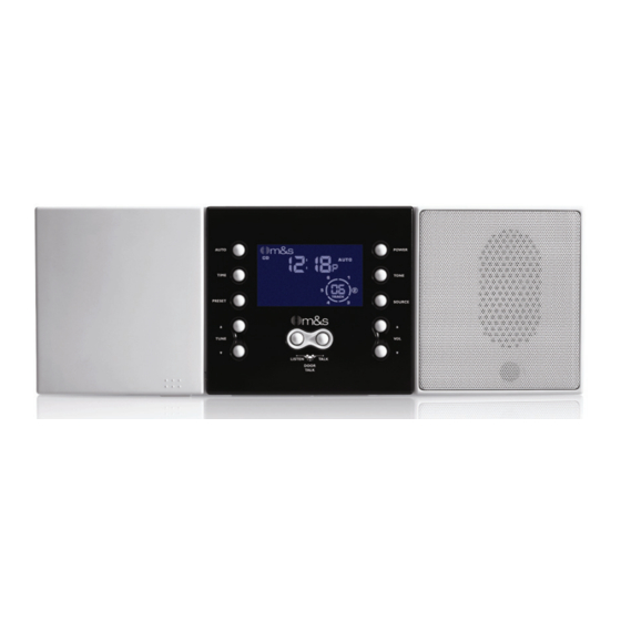
M&S Systems dmc1 Finish-Out Instructions Manual
M&s systems music communications system finish-out instructions dmc1
Hide thumbs
Also See for dmc1 Finish-Out:
- Owner's manual (24 pages) ,
- Instructions manual (16 pages) ,
- Rough-in instructions (8 pages)
Summary of Contents for M&S Systems dmc1 Finish-Out
- Page 1 Finish-Out Instructions www.mssystems.com | 800.421.1587 | www.mssystems.com Page...
- Page 2 Introduction Designed for installation in new home, the dmc1 is a whole-house music communications system. It is designed to provide years of enjoyment and service to the homeowner. M&S audio products are backed with more than 50 years of experience in the design and manufacture of precision acoustical equipment for the home.
-
Page 3: Important Safety
FOR CONTINUED PROTECTION AGAINST RISK OF FIRE REPLACE THE FUSE IN THE POWER SWITCH MODULE ONLY WITH SAME TYPE 6 AMP, 120 VOLT FUSE. THE dmc1 MUST BE INSTALLED BY A M&S SYSTEMS DEALER OR INSTALLERS, AND MUST CONFORM TO ALL LOCAL BUILDING AND ELECTRICAL CODES. - Page 4 Finish out the dmc1 system after the application of wall covering • material. Do not power up the dmc1 master until all remote stations and • speakers are connected. Do not connect a CAT-5 wire if you are unsure of it terminating •...
- Page 5 • Systems dealer or installer conduct a safety check to ensure the system is in proper operating condition. Use only a damp cloth to clean the dmc1 master and room stations. • Do not use liquid cleaners or aerosol cleaners.
- Page 6 Some screw terminals have more than one wire connected to them. Mount each room station to its mounting ring using the two screws provided with each dmc1 room station as shown in figure 2. Patio Station – DMC1RW At each patio station location, strip approximately 4 inches of jacket from the CAT5 wire and separate the colored conductors.
- Page 7 Use the labels provided to mark respective cables. Connect the cables to the plate as shown in figure 5 and mount the plate using the two screws provided. www.mssystems.com | 800.421.1587 | Page Figure 5 - External source wiring www.mssystems.com dmc1 Figure 4 - Volume control wiring to dmc1...
-
Page 8: Door Stations
Insert each wire pair into the correct connector location and close connector (see figure 7). Insert each cable connector into its proper location on the dmc1 master. Note: Verify that the outdoor patio speaker is connected into the Patios station cables location only. - Page 9 Figure 9 - Third hand assembly (MS4DCX/MS4DCXSC) to the red and black door speaker terminals on the dmc1 master as shown in figure 10. Insulate the bare wires using some of the jacket material to prevent shorting to the circuit board.
-
Page 10: Antenna Connection
Antenna Connection Connect the FM dipole twin lead antenna to the FM 300 Ohm terminals on the dmc1 master as shown in figure 10. Connect the orange AM antenna wire to the AM terminal on the master. Wireless Remote Control Connection... - Page 11 Mount the volume control to the single gang box using the two screws provided with the volume control (refer to figure 15). www.mssystems.com | 800.421.1587 | Page www.mssystems.com dmc1 Figure 12 – MS7XSC Wiring Figure 15 – Volume control mounting...
-
Page 12: Satellite Speakers
Secure the amplifier to the wall in the www.mssystems.com | 800.421.1587 | Page Figure 14 – Mono wiring connections Figure 16 – Speaker connections locations. Once the location of the stud has been verified, remove the screws. Remove the www.mssystems.com dmc1... - Page 13 VOLUME CONTROL PREAMP WIRING DAMAGE dmc1 Connection Locate the MS7X5SC cable from the dmc1 master. Connect each of the 7 colored wires and shield drain wire from the MS7XSC cable to the 8 pin terminal block as shown in figure 18. Plug the 8 pin connector into the jack labeled...
-
Page 14: Other Sources
Plug in the RCA phono plugs to the jacks as marked for the source equipment. Figure 21 shows a typical installation using the AWP/AWPRX audio wall plate installation kit. www.mssystems.com | 800.421.1587 | Page Figure 21 – AWP audio plate connections www.mssystems.com dmc1 Figure 20 – Jumper connections to dmc1... - Page 15 Owners Manual shipped with the master unit. If any difficulties are encountered, recheck all connections. If after reviewing these instructions and you are unable to resolve any problems, contact technical support at 1-800-421-1587. Figure 22 - DMC1 speaker cover installation www.mssystems.com | 800.421.1587 | Page www.mssystems.com...
-
Page 16: M&S Systems 2-Year Warranty
This limited warranty gives you specific legal rights, and you may also have other rights, which vary from state to state. www.mssystems.com | 800.421.1587 | Page www.mssystems.com dmc1 116002 C...


