Table of Contents
Advertisement
Advertisement
Table of Contents

Summary of Contents for Dahua DH-HAC-HFW3220EN-Z
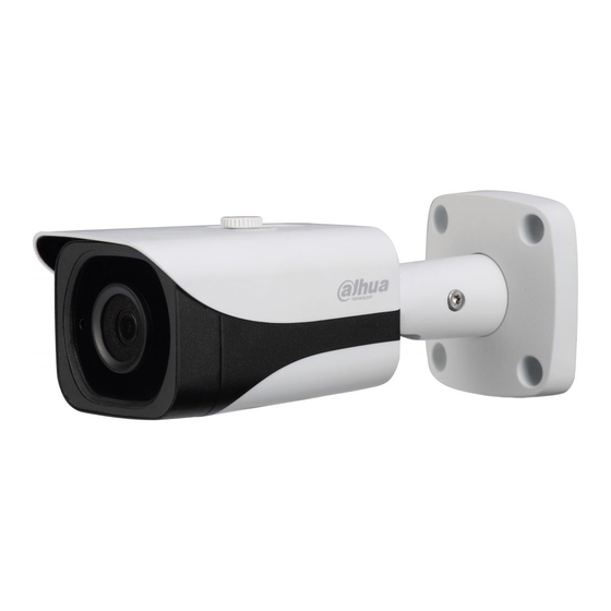
- Page 1 HDCVI Motorized Vari-focal IR Waterproof Fixed Camera User’s Manual Version 1.0.0...
-
Page 2: Table Of Contents
Table of Contents General Introduction ........................1 Overview ........................1 Features ......................... 1 Device Framework ........................2 Framework and Dimension ..................2 Structure Component ....................2 Lens Zoom Adjustment ....................3 Installation............................ 4 Menu ............................. 6 HDCVI Local Settings ....................6 4.1.1 Control Coaxial Device .................... - Page 3 Welcome Thank you for purchasing our HDCVI camera! This user’s manual is designed to be a reference tool for your system. Please read the following safeguard and warnings carefully before you use this series product! Please keep this user’s manual well for future reference!
- Page 4 Important Safeguards and Warnings 1.Electrical safety All installation and operation here should conform to your local electrical safety codes. The power shall conform to the requirement in the SELV (Safety Extra Low Voltage) and the Limited power source is rated 12V DC in the IEC60950-1. We assume no liability or responsibility for all the fires or electrical shock caused by improper handling or installation.
- Page 5 Please shut down the device and then unplug the power cable before you begin daily maintenance work. Use the dry soft cloth to clean the device. If there is too much dust, please use the water to dilute the mild detergent first and then use it to clean the device. Finally use the dry cloth to clean the device. Please put the dustproof cap to protect the CMOS component when you do not use the camera.
- Page 6 Applicable model This manual can be applied to the following model: DH-HAC-HFW3220EN-Z DH-HAC-HFW3120EN-Z DH-HAC-HFW3220EN-ZH DH-HAC-HFW3120EN-ZH DH-HAC-HFW3220EP-Z DH-HAC-HFW3120EP-Z DH-HAC-HFW3220EP-ZH DH-HAC-HFW3120EP-ZH HAC-HFW3220EN-Z HAC-HFW3120EN-Z HAC-HFW3220EN-ZH HAC-HFW3120EN-ZH HAC-HFW3220EP-Z HAC-HFW3120EP-Z HAC-HFW3220EP-ZH HAC-HFW3120EP-ZH...
-
Page 7: General Introduction
1 General Introduction 1.1 Overview This series HDCVI camera conforms to the HDCVI standard. It supports video signal high- speed long distance transmission without any delay. It can be controlled by the DVR conforming to the HDCVI. 1.2 Features High-performance CMOS image sensor, megapixel definition. -
Page 8: Device Framework
2 Device Framework 2.1 Framework and Dimension Please refer to the figure2-1 for dimension information. The unit is mm. Figure 2-1 2.2 Structure Component Figure 2-2... -
Page 9: Lens Zoom Adjustment
See Sheet 2-1 for more details about ports. Cable Port Name Function Color Green ALARM_NO On-off alarm output end. Orange ALARM_NC On-off alarm output end. ALARM_IN Alarm signal input end. Black ALARM_GND Alarm signal input GND. Brown, It can realize the switch from HD video output to SD White SD/HD Switch video output when it is short circuit SD/HD switch... -
Page 10: Installation
3 Installation Important Before the installation, please make sure the installation surface can sustain at least 3X weight of the bracket and the camera. Step 1 Select installation mode, install camera bracket according to the exact installation mode. Note: First please pull the cable through exit hole on the installation surface or the bracket before installing the bracket. - Page 11 Figure 3-1...
-
Page 12: Menu
4 Menu 4.1 HDCVI Local Settings This series HDCVI camera can adjust OSD menu via coaxial control. 4.1.1 Control Coaxial Device After connected the camera to the HCVR, from Main Menu-> System ->PTZ, you need to select the channel number to access and set control mode as HDCVI and the protocol as DH- SD1. -
Page 13: Open Menu
Figure 4-2 4.1.3 Open Menu On the preview interface, right click mouse and then select PTZ; you can see an interface shown as below. See Figure 4-3. Figure 4-3 Click Iris “+” to open menu or confirm current operation. Click up/down button to select all the parameters on the left pane of the first-level menu. Click left/right button to set the corresponding values on the right pane of the parameters. -
Page 14: Menu List
The operation interface above is just an example of HCVRHG-AF series, the operation interface may differ according to different back-end devices; please refer to corresponding HCVR manual for detailed operations. Users can also adjust OSD menu via 5-direction buttons. The exact operation is as follows: press the middle button for about 2 seconds, and the OSD menu will display on the monitor screen. - Page 15 The 1 The 2nd The 3 Exposure Exposure Gain Max 0~100 Auto Mode Gain Min 0~100 Return/Exi Note: For the 2nd and the 3rd menu, when you click Exit button to exit, system saves current setup by default. Low Noise Gain Max 0~100 Return/Exi...
- Page 16 The 1 The 2nd The 3 Besides, there are no exposure modes as anti-flicker and low noise. Return/Exi White Auto Balance Blue gain 1~100 Manual Red Gain 1~100 Return/Exi Night Indoor Outdoor Day/Night Day/Night 1~100 Auto Waiting Note: 1~15 time the 2nd menu Return/Exi is only valid to...
- Page 17 The 1 The 2nd The 3 Size Note: Use direction buttons to adjust position and zone size. Restore Default Return/Exit 485 Setup Address 1~254 Apply Return/Exit System Version XXXXXXXXX Info Return/Exit Return/Exit Reset Exit Note: The menu list above is an example for 1080P series, the only difference of the menu list for 720P series is about “Video Mode”, which shows that 720P series support 720P@25, 720P@30, 720P@50, 720P@60.
-
Page 18: Appendix Toxic Or Hazardous Materials Or Elements
Appendix Toxic or Hazardous Materials or Elements Toxic or Hazardous Materials or Elements Component Name Cr VI PBDE Circuit Board ○ ○ ○ ○ ○ ○ Component Device ○ ○ ○ ○ ○ ○ Construction Material ○ ○ ○ ○ ○...


